Honeywell Thermostat Wiring Diagrams
Honeywell thermostat wiring diagrams are essential for installing and troubleshooting your heating and cooling system. These diagrams provide a visual representation of how to connect the wires from your thermostat to your HVAC system. You can find Honeywell thermostat wiring diagrams in the user manual, on the Honeywell website, or through online resources.
Types of Thermostats
Honeywell offers a wide range of thermostats, each designed for specific HVAC systems and features. Understanding the different types of thermostats is crucial for selecting the right one for your needs and ensuring proper wiring. Here’s a breakdown of common thermostat types⁚
- Non-Programmable Thermostats⁚ These basic thermostats allow you to set a desired temperature, but they don’t offer any scheduling or automation features. They are generally the most affordable option but lack energy-saving capabilities.
- Programmable Thermostats⁚ Programmable thermostats offer scheduling options, allowing you to set different temperatures for different times of the day or week. This can help you save energy by automatically adjusting the temperature when you’re away from home or asleep.
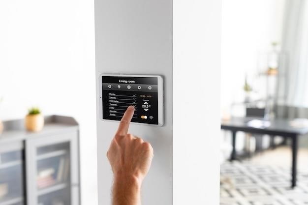
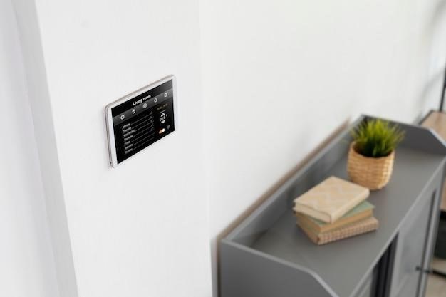
- Smart Thermostats⁚ Smart thermostats are the most advanced type, offering features like Wi-Fi connectivity, remote control, and learning capabilities. They can automatically adjust the temperature based on your preferences, weather conditions, and even your location. Smart thermostats often have a touchscreen interface and can be integrated with other smart home devices.
- Multistage Thermostats⁚ Multistage thermostats are designed for multi-stage HVAC systems, which have multiple heating and cooling stages. These thermostats allow you to control the different stages of your system, providing more precise temperature control.
- Heat Pump Thermostats⁚ Heat pump thermostats are specifically designed for heat pump systems. They have additional terminals for controlling the auxiliary heat and reversing valve, ensuring proper operation of your heat pump.
Choosing the right type of thermostat depends on your individual needs and preferences. Consider your budget, desired features, and the type of HVAC system you have when making your decision.
Wiring Diagrams for Common Systems
Honeywell thermostat wiring diagrams are essential for connecting your thermostat to your HVAC system. These diagrams vary depending on the type of system you have, such as forced air, heat pump, or hydronic. Understanding the specific wiring diagram for your system is crucial for a successful installation and proper operation.
Here are some common HVAC systems and their corresponding wiring diagrams⁚
- Forced Air Systems⁚ These systems use a blower to circulate air heated by a furnace or cooled by an air conditioner. The wiring diagram for a forced air system typically includes wires for power (R), heating (W), cooling (Y), fan (G), and common (C).
- Heat Pump Systems⁚ Heat pumps use a single unit to both heat and cool your home. The wiring diagram for a heat pump system will include terminals for power (R), heating (W), cooling (Y), fan (G), common (C), auxiliary heat (E), and reversing valve (O/B).
- Hydronic Systems⁚ These systems use water to circulate heat throughout your home. The wiring diagram for a hydronic system will typically include wires for power (R), heating (W), and common (C).
It’s important to note that wiring diagrams can vary depending on the specific model of thermostat and HVAC system. Always refer to the manufacturer’s instructions or consult a qualified electrician if you’re unsure about the wiring.
Honeywell Home T4 Pro Thermostat Wiring Diagrams
The Honeywell Home T4 Pro thermostat is a popular choice for homeowners seeking a smart and user-friendly thermostat. Understanding the wiring diagrams for this thermostat is essential for a successful installation. The T4 Pro supports various HVAC systems, including forced air, heat pumps, and hydronic systems.
The T4 Pro thermostat typically has terminals for power (R), heating (W), cooling (Y), fan (G), and common (C). Additionally, it may include terminals for auxiliary heat (E), reversing valve (O/B), and other system-specific connections. The specific wiring diagram for your T4 Pro thermostat will depend on your HVAC system and the type of wires you have.
To ensure proper installation, it’s recommended to refer to the T4 Pro’s user manual or the Honeywell website for specific wiring diagrams. These resources provide detailed instructions and illustrations for connecting the wires to the thermostat and your HVAC system. If you’re unsure about the wiring, it’s best to consult a qualified electrician for assistance.
Transformer System, 1H/1C: Oil Furnace

A transformer system, often referred to as a 1H/1C system, is a common setup for oil furnaces. It utilizes a transformer to reduce the voltage from the main power supply to a lower voltage (typically 24 volts) that is compatible with the thermostat. This system is relatively straightforward to wire, and the Honeywell thermostat wiring diagram for this configuration usually involves five wires⁚ R, W, G, C, and Y.
The R wire is connected to the transformer’s secondary side, providing power to the thermostat. The W wire connects to the heat relay, which controls the oil burner. The G wire connects to the blower motor, controlling the fan. The C wire is the common wire, grounding the system. The Y wire is typically not used in a 1H/1C oil furnace system, as it is primarily for cooling.
It’s important to note that the specific wiring diagram may vary slightly depending on the Honeywell thermostat model and the specific features of your oil furnace system. Always consult the user manual or the Honeywell website for the correct wiring diagram for your particular setup.
Hot Water Boiler, Heat Only

A hot water boiler system provides heat through a circulating hot water loop. The Honeywell thermostat wiring diagram for this configuration will typically involve five wires⁚ R, W, G, C, and O/B. The R wire provides power to the thermostat from the transformer. The W wire controls the boiler’s circulating pump, switching it on and off to regulate the water temperature. The G wire controls the blower motor, ensuring proper air circulation throughout the system. The C wire is the common wire, providing a ground connection.
The O/B wire is a bit more complex. It serves as a secondary heat relay, commonly used in conjunction with a zone valve. When connected to a zone valve, the O/B wire acts as a signal to open or close the valve, directing the hot water to the specific zone needing heating. However, if your hot water boiler system doesn’t utilize a zone valve, the O/B wire might not be needed.
It’s essential to refer to the Honeywell thermostat wiring diagram specific to your model and system for accurate wire connections. Incorrect wiring can lead to system malfunctions or even damage to your heating equipment. Always consult the user manual or the Honeywell website for the correct wiring diagram for your particular setup.
Hot Water Heat with Power Open/ Power Closed, Series 20 Zone Valve
This configuration involves a hot water boiler system equipped with a Series 20 zone valve that controls the flow of hot water to different areas of your home. The Honeywell thermostat wiring diagram for this setup will typically involve six wires⁚ R, W, G, C, O/B, and a separate wire for the zone valve. The R wire provides power to the thermostat from the transformer, while the W wire controls the boiler’s circulating pump, turning it on and off to regulate the water temperature.
The G wire controls the blower motor, ensuring proper air circulation. The C wire provides a common ground connection for the system. The O/B wire acts as a secondary heat relay, working in tandem with the zone valve. In a power open configuration, the O/B wire provides a signal to open the zone valve when heat is required. Conversely, in a power closed configuration, the O/B wire signals the zone valve to close, shutting off the hot water flow to that area.
The sixth wire is dedicated to the zone valve itself, receiving a signal from the thermostat to open or close the valve. Refer to the specific Honeywell thermostat wiring diagram for your model and system to ensure accurate wire connections. Improper wiring can lead to system malfunctions or damage to your heating equipment. Always consult the user manual or the Honeywell website for the correct wiring diagram for your specific setup.
2H/1C: Heat Pump with Electric Aux Heat
This setup involves a heat pump system with an auxiliary electric heating element. The Honeywell thermostat wiring diagram for this configuration includes several wires, each serving a specific function. The R wire provides power to the thermostat from the transformer, while the C wire acts as a common ground connection for the system.
The Y wire controls the heat pump’s compressor, while the W wire controls the auxiliary electric heating element. The G wire controls the blower motor, ensuring proper air circulation. An additional wire, labeled “E” or “Aux,” is connected to the auxiliary electric heating element, providing a dedicated signal for its operation.
When the thermostat calls for heat and the heat pump’s capacity is insufficient, the auxiliary electric heating element kicks in to provide additional warmth. The “E” or “Aux” wire ensures that the auxiliary heating element operates only when needed. The wiring diagram for this system will vary depending on the specific Honeywell thermostat model. It’s crucial to consult the correct wiring diagram for your model to avoid incorrect connections that could lead to system malfunctions or damage.
Wiring Conventional Systems⁚ Forced Air and Hydronics
Honeywell thermostat wiring diagrams for conventional forced air and hydronic systems often follow a standardized format, making installation and troubleshooting relatively straightforward. These systems typically involve a single-stage heating or cooling system, with the thermostat controlling the operation of the furnace or air conditioner.
The wiring diagram will typically show the following terminals⁚ R (power), C (common), W (heating), Y (cooling), and G (fan). The R wire provides power to the thermostat from the transformer, while the C wire serves as a common ground for the system. The W wire controls the heating element or valve, while the Y wire controls the cooling compressor or valve. The G wire controls the fan, ensuring air circulation within the system.
For forced air systems, the thermostat signals the furnace or air conditioner to turn on or off based on the set temperature. For hydronic systems, the thermostat controls the flow of hot water to the radiators or baseboard heaters. The wiring diagram will clearly indicate which wires connect to which terminals, ensuring a proper connection between the thermostat and the HVAC system.
Troubleshooting and Support
When dealing with Honeywell thermostat wiring diagrams, troubleshooting can be a common occurrence. If your thermostat isn’t functioning correctly, understanding the wiring diagram can help you identify potential issues. Common problems include incorrect wire connections, faulty wires, or a malfunctioning thermostat. It’s important to always disconnect power to the system before working on any wiring to avoid electrical shock.
If you’re experiencing issues with your thermostat, Honeywell offers a variety of resources to assist you. You can consult the user manual for your specific thermostat model, which will often include troubleshooting tips and diagrams. Honeywell’s website also provides a wealth of information, including online support forums, FAQs, and even video tutorials. In addition, Honeywell offers a dedicated customer service line for technical support.
If you’re unable to resolve the issue yourself, it’s always recommended to consult with a qualified HVAC technician. They can diagnose the problem, make necessary repairs, and ensure your system is operating safely and efficiently. Remember, a properly wired thermostat is essential for a comfortable and energy-efficient home.
Common Wire and Compatibility
Understanding the common wires and their functions is crucial when working with Honeywell thermostat wiring diagrams. The most common wires found in HVAC systems are R (power), C (common), W (heating), Y (cooling), G (fan), and O/B (optional). These wires connect to the thermostat and the HVAC system’s control board, relaying signals to activate heating, cooling, and fan functions.
Compatibility is another important aspect to consider. Not all Honeywell thermostats are compatible with every HVAC system. Some thermostats may require specific wiring configurations or features, such as a C wire for power. Before installing a new thermostat, it’s essential to ensure compatibility with your existing system. Checking the thermostat’s specifications, consulting the user manual, or contacting Honeywell customer support can help determine compatibility.
When working with wiring diagrams, it’s crucial to identify the type of system you have (e.g., forced air, heat pump, hydronic). Each system may have unique wiring configurations, and using the correct diagram is essential for a successful installation. Always double-check the wiring connections before turning the power back on to avoid potential damage or malfunctions.
Connecting Wires to the Thermostat
Connecting wires to your Honeywell thermostat is a critical step in the installation process. Carefully follow the wiring diagram provided for your specific thermostat model and HVAC system. Before connecting any wires, ensure the power is turned off at the breaker box to prevent electrical shock.
Locate the terminal block on the thermostat, which usually has labeled terminals (e.g., R, C, W, Y, G). Match the labeled wires from your HVAC system to the corresponding terminals on the thermostat. Use a screwdriver to loosen the terminal screws, insert the wire into the terminal block, and then tighten the screw to secure the wire. Make sure each wire is securely connected and that the connections are not loose or frayed.
Pay attention to the wire colors, as they often indicate specific functions. For instance, a red wire typically represents the “R” (power) terminal, while a yellow wire might correspond to the “Y” (cooling) terminal. However, it’s always best to refer to the wiring diagram for accurate color-coding information. Double-check all connections before turning the power back on. If you encounter any difficulties or have questions, consult the user manual or contact Honeywell customer support for assistance.
Mounting and Installation
Mounting and installing your Honeywell thermostat is a straightforward process, typically involving a few simple steps. First, choose a suitable location for your thermostat, preferably a central location away from direct sunlight, drafts, and heat sources. Ensure the wall is level and free of obstructions before mounting the thermostat.
Some thermostats come with a wall plate that can be used as a template for marking the mounting holes. Use a pencil to mark the locations for the mounting holes, then drill pilot holes using a drill bit that is slightly smaller than the screw size. Insert wall anchors if necessary, especially for drywall surfaces, to provide secure mounting.
Align the thermostat with the marked holes, ensuring it is level, and then secure it to the wall using the provided screws. Once the thermostat is mounted, connect the wires to the terminal block, following the wiring diagram. After connecting the wires, turn the power back on at the breaker box and test the thermostat to ensure it is functioning correctly. If you have any questions or encounter difficulties, consult the user manual or contact Honeywell customer support for assistance.


